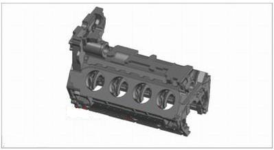
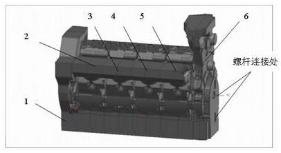
First, the establishment of casting model Analyze the 2D product drawings of the cylinder parts, find out the main structure, use CAD technology, first establish the main structure model of the parts, and then build those small functional models on the main structure (main model). Finally, these The main model and the functional small model are Boolean operations, and the three-dimensional solid geometric model of the cylinder part can be obtained. Casting process for geometric model: machining allowance is added on the machined surface, sharp edges are rounded, and the positioning clamping process boss used for cold working is set to scale the entire geometric model (according to the casting environment and casting method and casting) The shrinkage rate is determined by the difference in material. This design enlarges the geometric model by 1.008 times, as shown in Figure 3. Figure 3 BF8L513 cylinder casting model designed with Pro/ENGINEER 3D software Second, the shape and core design of the casting model The traditional casting mold design and core box mold design are familiar to everyone. The outer mold and core box mold produced by this old method, due to the abstraction of the two-dimensional engineering drawings and the separation of the core mold design, it is difficult for them to assemble and reflect the precision required by the two-dimensional engineering drawings of the cylinder. The effect, which in turn affects the overall performance of the product. The use of 3D solid composite modeling technology can solve the problems that are difficult to solve in traditional mold design. The first is the accuracy of the mold cavity. When performing the core separation of the casting model, the following steps are required: (1) Establish a physical cube that can fully accommodate the casting model in three dimensions; (2) using the cylinder casting model as a tool entity and performing Boolean subtraction with the target entity cube to obtain an initial core combination entity; (3) Using the shearing function in the software, the part connecting the core head and the outer shape is cut into two separated entities (no characteristic parameters), that is, the sand core assembly and the reverse mold of the mold are obtained; (4) According to the molding process of the sand core, the combination of the sand core is reasonably distributed into a plurality of small sand cores, and the cores are separately formed. (See Figure 4) Figure 4 computer 3D simulation sand core assembly diagram 1 is the end core; 2 is the first cylinder core; 3 is the second cylinder core; 4 is the third cylinder core; 5 is the fourth cylinder core, using the manual resin sand core; 6 is the transmission box core, using the hot core box Core making. The assembly sequence is as follows: the sand core is placed on the core tire in the order of the labels, and the Screw is put on and tightened. Previous page next page
Cutting Board Rack,Cutting Board steel rack,Cutting Board Organizer rack,Stainless Steel Cutting Board Rack,Chopping Board Rack,Stainless Steel Chopping Board Rack, The materials are used 304 stainless steel, easy to clean, never rust!
Kichen Rack is made of high quality 304 stainless steel, This kind of material steel luxury, never rust, resist corruption, easily clean, safe, healthy and durable. Prevent rust or chemicals from contaminating food and damaging health
Cutting Board Rack,cutting board storage rack,cutting board holder,Stainless Steel Cutting Board Rack,Chopping Board Rack Shenzhen Lanejoy Technology Co.,LTD , https://www.wire-spring.com
