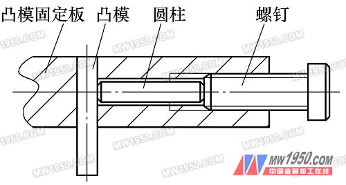
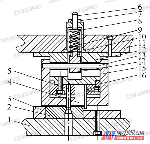
Figure 3 convex mold fixing method diagram Figure 4: Composite drawing of bending rib groove punching compound 1. Lower die plate 2. Die 3. Die die plate 4. Pressing punch 5. Punching punch 6. Adjusting screw 7. Fastening nut 8. Spring top plate 9. Discharge spring 10. Die shank 11. Upper mold base plate 12. Upper mold back plate 13. Cylindrical pin 14. Spring washer 15. Guide sleeve discharge plate 16. Punch fixing plate (2) Mold Features The mold has the advantages of compact design, simple production and convenient mold repair. The adjustable spring cylindrical guide pin structure is also suitable for floating upper dies of small punches. The guide sleeve discharge plate 15 and the convex mold fixing plate 16, the guide sleeve discharge plate 15 and the convex mold 5 are all matched with a small gap of H7/f6, and the purpose is to protect and guide the convex mold. For the sake of simplicity, the guide sleeve and the discharge plate are driven out on the lathe. 4. U-shaped transverse bending mode (1) Design concept U-shaped parts must bend two corners at a time. The commonly used U-shaped bending die is suitable for the left and right symmetry of the blank, otherwise the workpiece will easily slide to the long end during bending. The piece is U-shaped in the shape of the head, and the angle is less than 90°, and the dimensional accuracy is high. It is preferable to clamp the large-area end between the punch and the top plate according to the shape of the product, and then bend it at a time. (2) Mold structure and working process The upper die of the die (see Fig. 5) adopts a floating type, and the square punch 12 is pressed into the square hole of the fixing ring by the spring 6, and is hoisted in the die shank by the ejector bolt 8 to ensure The correct position of the mold and move up and down. The lower die is formed by an L-shaped bending die provided with a top plate, and the movable platen 3 is added. An automatic pushing device 13 is arranged between the upper and lower dies, and the inclination of the device remains unchanged as the slider moves up and down. During work, the workpiece is placed in the slot of the ejector lever 18, the slider of the press is descended, the upper die contacts and presses the workpiece, and the upper die continues to descend. Since the spring 6 elastic force is greater than the sum of the elastic force of the spring 17 and the bending deformation force, the ram is forced. The workpiece is initially bent into an L shape until the ejector pin contacts the lower mold fixing plate, the slider continues to descend and the upper mold presses the workpiece, and the fixed ring contacts the end of the movable platen to swing the movable platen until the The workpiece package is formed in the upper mold while the screw 4 contacts the jack bolt 8, forcing the workpiece to be flattened in the square punch 12. Previous page next page Flexible Glass Fiber Ruler Tape Measure,Steel Ruler Tape Measure,New Nylon Ruler Tape Measure SHANGQIU STAR TOOLS CO.,LTD , https://www.loadstartape.com
