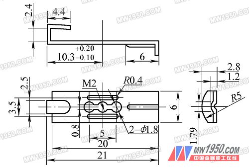
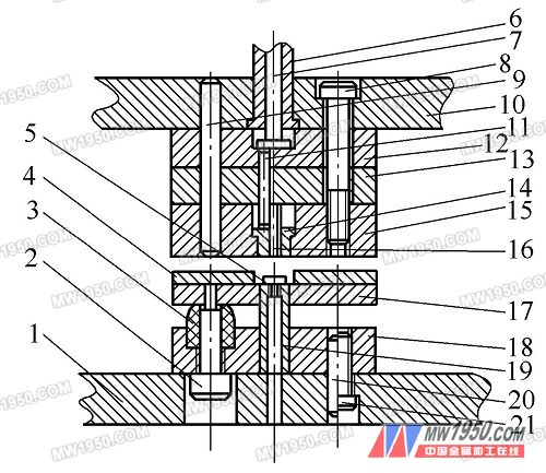
Figure 1 Parts drawing Through analysis, it should be considered from the following aspects: 1 The number of processes should be reduced to minimize the accumulation error between processes. 2 The slot die should focus on the strength and stability of the punch. 3 Bending forming should be changed to one-time forming to ensure the dimensional accuracy of the parts. 1. Improved design and manufacturing solutions In view of the above situation, according to the minimum punching value of the material and the minimum hole margin of the blanking part, it is decided to change the original 8 processes into 3 forming processes: 1 using the blanking punching composite die. 2 The curved ribs are used to punch the composite mold. 3 U-shaped transverse bending mode is used. 2. Blanking and punching composite die The mold is a flip-chip composite mold (see Figure 2). The upper mold adopts the push rod to discharge, and the punching waste is leaked from the convex and concave mold in the lower template hole, and the working principle is the same as that of the ordinary mold. In the design, considering the strength and stability of the punches 16, 19, three measures are taken in the structure: 1 improve the matching precision of the top piece 14 and the die 15 and the punch 16, and select a small clearance fit of H7/f6, The top member not only functions as a top member but also functions as a punch sheath and guide. 2 In order to achieve the processing precision, the top member 14 steps are inlaid and riveted, and can be cut by wire. 3 The punch 16 is formed by direct wire cutting of a high speed steel square blade, and the fixing method thereof is shown in FIG. 3. Bending rib grooving composite die (1) Mold structure and working process The upper mold of the composite mold (see Fig. 4) is different from the general four-column elastic discharge unloading form, and a cylindrically guided elastic pressure discharge structure is designed. The guide sleeve discharge plate 15 and the spring washer 14 are coupled by a cylindrical pin 13, and a long hole is formed in the upper die pad 12, and the punch fixing plate 16 is coupled with the upper die pad by screws. The die fixing plate 3 is higher than the die 2, and can fix the lower die and the positioning function of the workpiece. When working, the upper die descends, and the guide sleeve unloading plate 15 presses the workpiece under the action of the spring 9. The bending embossing punch 4 first bends the workpiece into a 90° angle, the slider continues to descend, and the punch 5 contacts the workpiece to start punching. The groove is then embossed. Figure 2: Blanking and punching composite die assembly drawing 1. Lower die seat plate 2. Unloading screw 3. Rubber 4. Stop material 5. Block pin Next page Modern Design Door Guards are suitable for all interior design styles. This Door Guards are available in different material for different budgets, with a variety of finish. Our Door Guards for All Purpose are durable and suitable for various residential, hotel, public and commercial places, etc. Swing bar door locks are security locking devices for swing-in doors, allow people inside the room to open the door few inches for identification or ventilation while providing privacy and security for guests and residents. Door latches also can be installed out of children's reach so they can't open the door by themselves, providing additional child-safe door security. Door Guard Latch,Door Guard,Car Door Guard,Screen Door Protector Leader Hardware Manufacturer Limited , https://www.leaderhardwarecn.com
Our unit has undertaken a small stamping and bending part of a factory as shown in Figure 1. The part is made of 1Cr18 Ni9 Ti stainless steel. The intermediate hole and two 0.8 mm wide grooves are used to adjust the screw after screwing into the M2 screw hole. Loose. The U-shaped angle of 2.4 mm is required to be less than 90°, and the distance from the center line to the curved edge of the M2 tap hole is ![]() . If single-step mold production is used, the process procedure is: blanking→punching→punching→leveling→bending→pressing rib→bending right angle→bending U shape a total of 8 processes. The process is not only low in work efficiency, but also difficult to ensure quality, especially when the punching die is easy to break when punching stainless steel. The surface of the 08F material can be replaced by chrome plating, but the material is inelastic, and the adjusting screw is easy to loosen after being screwed into the M2 screw hole.
. If single-step mold production is used, the process procedure is: blanking→punching→punching→leveling→bending→pressing rib→bending right angle→bending U shape a total of 8 processes. The process is not only low in work efficiency, but also difficult to ensure quality, especially when the punching die is easy to break when punching stainless steel. The surface of the 08F material can be replaced by chrome plating, but the material is inelastic, and the adjusting screw is easy to loosen after being screwed into the M2 screw hole. 

6. Mold handle 7. Dip rod 8. Screw 9, 20. Pin 10. Upper die plate
11.Putter 12. Upper die pad 13. Punch fixing plate 14. Top piece 15. Die
16. Punch 17. Discharge plate 18. Male and female mold fixing plate 19. Male and female mold 21. Screw