The implementation of the scheme is in a soft soil roadbed with a bearing capacity of 50 kPa. The whole bridge supports 10 temporary buttresses. The base height of each buttress is 29 m and the thickness is 06 m. Four workpieces are pre-buried at a distance of 2 m2m. Then the military pier and the embedded parts are erected. After the military pier is set up, the 1266m box girder is erected and the box girder is placed on the box girder. The I-beam is divided into three parts: under the center line of the chord, the temporary support is set according to the pre-cavity of the steel beam before the erection at each large node to facilitate the construction; the trajectory of the beam is 718cm on both sides of the bridge axis. Support, laying the sleepers on the top before erecting, and then setting the gauge distance according to the track of the Ziniping car; 3m away from the center (this is the support of the crane on the beam) with the I-beam connected into a whole, military pier and The foundation is fixed, and the I-beam and the temporary pier are fixed to enhance the working capacity of the crane on the beam. Before setting up, you need to lay the sleepers to set the gauge. Since the bridge is under the road, it is forbidden to drop the object on the beam. The entire bracket must be covered with scaffolding. The armrests should be installed 15m on both sides and the scaffolding board should be fully covered (the side panels are also full of side panels) to prevent the nails or bolts from being removed. The side fell into the road. Construction steps 1) 04 pier foundation excavation, excavation to the elevation of 29m, pour concrete to the elevation of 35m, and embed the embedded parts. 2) Site site finishing. Leveling 83 and 85 piers on the construction site and compacting them to facilitate the laying of the track and the on-site assembly of the steel beams. 3) Temporary pier erection. The pier structure is a six-five pier structure, the lower part is firmly connected with the embedded parts, the upper pad beam and the 1266m box girder are connected by bolts or tie rods, and the I55 I-beam and the military pier are connected by tie rods. 4) Laying of the track. After leveling the site, two sets of rails were laid, and the rails were laid at intervals of 50 cm to form the sleeper rails. 5) On the bracket, there are beam crane track and transport beam track. The beam track is in the middle, the crane track is close to the lower chord, and the front two legs and the back two legs of the beam crane are tightened by the reverse chain. The side chain is stressed by each %200kN. Steel beams are pre-spliced. Pre-stamping first pre-stamp, chord pre-stitching is generally set up with sleepers, the height is determined by the height of the gusset plate, generally about 15m, the upper part of the big slab is pre-spliced, with the necessary small Pieces, easy to assemble on the beam. The stringer is generally padded with a layer of sleepers underneath, and the two longitudinal members are assembled into a whole by diagonal methods. Flat assembly is generally a combination of two on the ground in advance. Assembly of steel beams on site. A rigid buttress is placed on the laid rail, and the steel beam is assembled on the rigid buttress. The lower part and the lower part are used according to the site conditions and the assembly, so that it becomes a stable structure as early as possible. The lower assembly sequence is as follows: the lower and lower lower chords are assembled under the lower longitudinal beam longitudinal beam; the upper assembly sequence is: the vertical longitudinal cross-connection on the upper chord of the diagonal pole vertical rod. Make a good job of the steel beam and the falling beam. After the steel beam is assembled, the beam should be dropped. First, the steel beam is jacked up at the top beam position of the steel beam with the jack, and the bracket below is removed. The layer is then placed on the support in the range of the jack stroke. Conclusion In the implementation of the disassembly-type beam crane on the full bracket on the steel truss frame, you should also pay attention to the 300m peripheral deceleration mark, at 50m with the peripheral gantry, mark on the bracket to ensure safety .
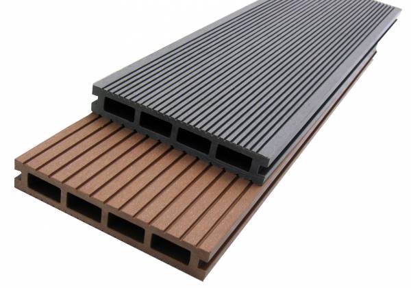
Co-Extruded Decking is made from high-strength wood and plastic composite. It`s UV-resistant and durable.
Size: 140*25mm,140*28mm,89*25mm. Solid and Hollow.
Color: Teak, Beech, Black Walnut, Coffee, Customized color.
Material component: 60% PVC+30% Wood Powder+10% special additives.
Surface: Smooth, Brushed, Scratched, Grain optional.
Specifications:
2. Longer usage/life cycle - resistant to rot and wood eating organisms
3. Stronger and more flexible than traditional wood products
4. Standard woodworking tools can be used
5. High degree of UV and color stability
6. Dimension stability against moisture and temperature. suitable from -40 to 60
7. Weather resistant, suitable from -40 to 60
8. Green ecological, Innovative technology, Lifestyle
9. Elegant nature wood grain texture and touch, with wood scent
10. Elegant and detailed shape design
11. Environmentally friendly -100% recyclable
Certificate: ISO9001, ISO14001, CE, SGS
Lifetime: 25 years
Warranty: 15 years
Package: Pallet with PVC soft flim
Pictures of Co-extruded Decking:
1. Saving time - easy maintenance and installation.

Co-extruded Decking
Co-Extruded Decking, Co-Extruded Composite Decking, WPC Co-Extruded Decking
Zhejiang Huaxiajie Macromolecule Building Material Co., Ltd. , http://www.pvcbuildingdeco.com