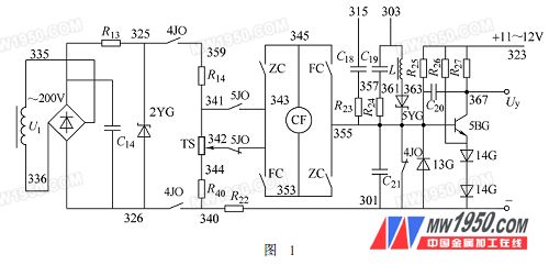
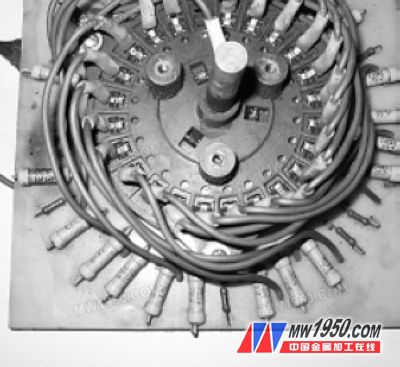
X2010A gantry milling machine is an indispensable equipment for our company to process square drill pipe or hexagonal drill pipe and mandrel punching. The feed motion of the table is to adjust the given potentiometer through the multi-stage switch on the operation panel. And the given voltage level for pole speed regulation, due to the long-term use of the multi-stage transfer switch bushing break, its dynamic and static contacts close and break, causing a given voltage sometimes, resulting in the movement of the table 窜Move, can't work properly. 1. Overview of the preamplifier portion of a given signal and signal Figure 1 shows the preamplifier part of the given signal and signal. The given power supply U1 is 200V, the rectified output is 250V, and the regulated output is 105V. The CF in the figure is the speed measuring machine, and the governor TS is the multi-stage switching switch. The total resistance of the governor is 10kΩ. By adjusting the potential of each point of the governor TS handle, the given voltage changes from high to low (or from low to high), given voltage and tachometer negative feedback and voltage and current. The differential negative feedback is compared and applied to the input terminal of the amplifier 5BG. After the amplifier is turned on, the DC control voltage Uy is output. Uy is compared with the sawtooth voltage, and then the transistor of the pulse forming step is controlled to be turned on and off, thereby outputting a synchronous pulse to control the conduction of the thyristor. Changing the magnitude of the control voltage Uy changes the timing at which the Uy intersects the sawtooth wave, so that phase shifting can be performed to control the magnitude of the output voltage and change the rotational speed of the motor. 2. Determination of the transformation plan From Fig. 2, we can see that when the governor handle is changed to a given voltage level, the opening and closing of the resistors of each stage is caused by the opening and closing of the multi-stage switching switch of the original circuit of Fig. 2 When the closing is realized, the bushing of the multi-stage changeover switch is broken, and the moving and static contacts are closed and time-broken, causing a certain voltage to be sometimes absent, causing the feed motion of the table to be shaken and unable to work normally. Since this kind of multi-stage switch has been eliminated, nowhere to buy, after analysis and calculation, it is decided to modify the given circuit of the equipment. The new circuit removes the multi-stage switch and decides to adopt the model WXD7-33-5W10kΩ, and the linear precision is ± A multi-turn potentiometer with a resistance tolerance of ±2% to ±5% is 0.1% to ±0.3%, and the multi-turn potentiometer TS of Fig. 2 is used for the given adjustment. A wire rope clamp (sometimes called a clip) is used to secure the loose end of the loop back to the wire rope. It usually consists of a U-bolt, a forged saddle, and two nuts. Two layers of wire rope are placed on the U-bolts. Then slide the saddle over the rope and attach to the bolts (the saddle includes two holes for the U-bolts). Nuts hold the unit in place. The wire rope is usually terminated using two or more clips depending on the diameter. A 2" (50.8 mm) diameter rope may require as many as eight.
The U.S. Navy and most regulatory agencies do not recommend using such clips as permanent terminals unless regularly inspected and retightened. Encyclopedia website: ewikizh.top
Wire Rope Clips,Wire Rope Clamp,Grips Clips And Clamps,Stainless Steel Wire Clips Jiangsu Hongze Stainless Steel Wire Rope Co., Ltd , https://www.hzrope.com

Figure 2 original circuit multi-level switch Previous page 1 2 Next page
There is an old saying: "A dead horse is without a saddle". This means that when installing the clips, the saddle portion of the assembly should be placed on the load bearing or "live" side of the cable, not the non-load bearing or "live" side of the cable. The "no power" side. According to U.S. Navy Manual S9086-UU-STM-010 Chapter 613R3, Wire and Fiber Ropes and Slings, "This is to protect the live or pressure-bearing end of the rope from pinching and damage. The flat bearing housing and body (saddle-shaped ) extension claws are designed to protect the rope and remain on the live end at all times."[18]
