Solar energy is an inexhaustible source of renewable energy. It is also a clean energy source that does not produce any environmental pollution. The use of solar energy is the fastest growing and most dynamic research field in recent years. It is one of the most highly anticipated projects. For this reason, people have developed and developed solar cells. One of the most critical steps in the production of crystalline silicon solar cells is to make very fine circuits on the front and back of the silicon wafer, and to export the photoelectrons out of the cell. This metal coating process is usually done by screen printing technology. Crystal silicon solar cell screen printing technology The crystalline silicon solar cell screen printing technology is the process that the conductive paste containing metal is imprinted on the silicon wafer to form a circuit or an electrode through the screen mesh hole. Typical crystalline silicon solar cells require multiple screen printing steps throughout the entire production process. In general, there are two different processes for screen printing on the front (contact line and busbar) and backside (electrode/passivation and busbars) of the battery. Solar cells are a symbolic product for the development and utilization of new energy and low-carbon environmental protection. Screen printing plays a very important role in the manufacturing process of the solar cell's front, back, and back electric fields. The screen-printed solar electrode process is now quite mature and has become the mainstream process screen printing method. Crystal silicon solar cell printing process The printing process begins with the placement of the silicon wafers onto the printing table. A very fine screen printing plate is fixed on the frame and placed above the silicon plate. The screen encloses other areas than the grid lines so that the conductive paste can pass through. The distance between the silicon wafer and the screen must be strictly controlled (referred to as print gap, or net spacing). Due to the need for a more slender metal wire on the front side, the mesh of the screen used for frontal printing is usually much smaller than that used for backside printing. The appropriate amount of slurry was placed on the screen, and the slurry was coated with a spatula so that it was evenly filled in the mesh. During the movement of the scraper, the slurry was extruded through the screen mesh to the silicon wafer. The temperature, pressure, speed and other variables of this process must be strictly controlled. After each printing is completed, the silicon wafer is placed in a drying oven to solidify the conductive paste. The wafers are then fed to a different press and more lines are printed on the front or back. After all the printing steps are completed, the silicon wafer is sintered in a high temperature furnace. Print on the front and back of the wafer Each solar cell has screen-printed wires on the front and back, and their functions are different. The front line is thinner than the back side; some manufacturers print the back side of the conductive line first, then flip the silicon side over and print the front side of the line, minimizing possible damage during processing. On the front side (facing the Sun side), most crystalline silicon solar cells are designed with very fine circuitry ("finger lines"), which transfers the photogenerated electrons from the active area to the larger acquisition wire - the "bus" Then, it is passed on to the circuit system of the component. The front finger line is much thinner than the back line (narrow to 80 μm), and because of this, the frontal printing step requires greater precision and accuracy. The printing requirements for the backside and frontside of the wafer are different and not technically strict. The first step in the backside printing process is to print a layer of aluminum-based conductive material instead of a very fine conductive grid. At the same time, light that is not captured can be reflected back to the battery. This layer can also "passivate" the solar cells, blocking the excess molecular pathways and preventing the flow of electrons from being trapped by these voids. The second step in the backside printing is to make busbars that are connected to external circuitry. Crystalline silicon solar cell screen printing standard index In order to increase the conversion rate of solar cells and reduce the shielding of the silver wires and the battery board, the width of the grid lines on the screen plate should be as narrow as possible, and too thin grid lines may cause the thickness of the conductive silver paste to be too thin, even It may be broken. Therefore, the grid width on the screen plate is generally between 80 and 120 μm. Due to the increased width of the conductive silver paste after printing, the printed silver paste has a width of 110-150 μm after sintering. In order to reduce its series resistance, the total weight of the silver wire printed on the battery board should be as low as possible, basically 0.01 ~ 0.02g. Printing pressure is 75 to 80 Newtons. The stretching tension of the screen is generally 28±2N. The life of the back electrode screen should be greater than 15,000 times, the life of the back electric field screen should be greater than 15,000 times, and the life of the positive electrode screen should be greater than 10,000 times. Crystal silicon solar cell wire mesh storage requirements Wire mesh should be stored in a constant temperature, constant humidity condition. Rapid temperature changes will cause the tension to drop. The excessive humidity will cause the degeneration of the latex, which will affect the use effect and even scrap. Specific storage conditions are: temperature 22±3°C, humidity 50%±10%. Before the use of the production workshop, the screens should be brought out in advance and left standing in the factory for more than 24 hours. When it is urgently needed, it should be ensured that the plant is left standing for more than 2 hours. The screen is always stored in a clean environment before leaving the factory, so it should be kept clean before use. The quality inspection process should be carried out in a relatively clean environment. After the quality inspection, it should be sealed in the original plastic bag and stored in the warehouse. Avoid dust contamination before use. The screen is very sensitive to vibrations. Any collision will cause the tension to drop or the net to be scrapped. Therefore, it should be handled gently during the movement and use to avoid any collision. The surface of the wire mesh is very fragile, and any blunt object may cause damage to the mesh yarn portion, causing a drop in tension, graphics damage, shortened life, or even scrapped. Therefore, during the movement and use, the surface of the mesh should be prevented from coming into contact with any blunt object. Therefore, the best way to store the screen is to use a dedicated shelf for vertical storage. If it is laid flat, it should not exceed 5 layers. The layers should be separated by a soft pad at the frame.
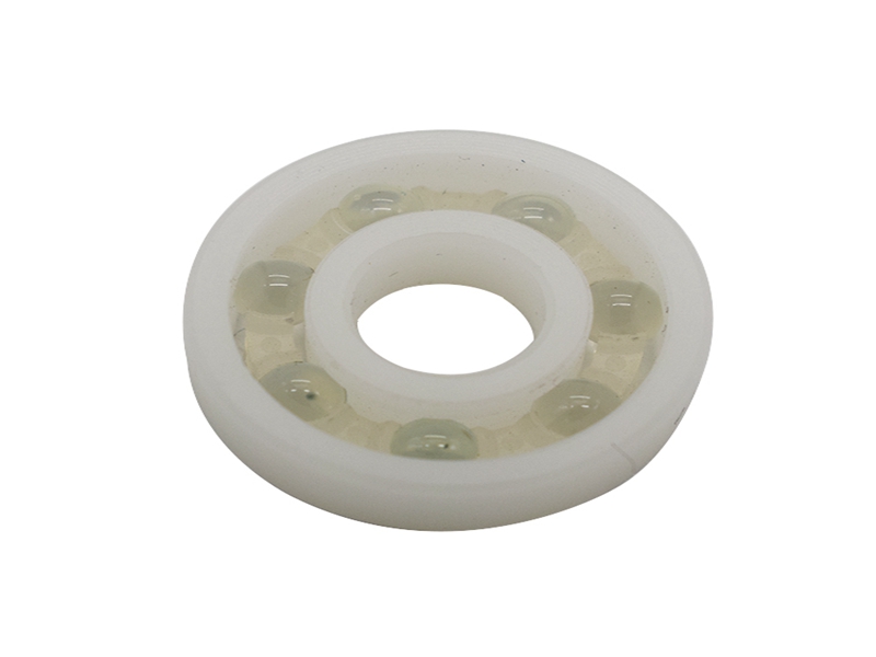
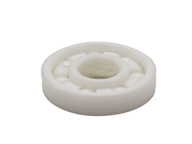
The full ceramic ball bearings listed below are supplied with rings and balls made from zirconium dioxide (ZrO2). These zirconia bearings are available as full complement (no cage) or with cages made from PTFE, PEEK or 316 stainless steel.
These are non magnetic, non-conductive and highly corrosion resistant to most chemicals although ZrO2 bearings are not recommended for prolonged contact with steam. Full complement bearings or those with a 316 stainless cage can be used up to 400°C while bearings with a PEEK or PTFE cage can cope with temperatures of up to 250°C. For temperatures below -70°C, PTFE or 316 stainless steel cages are preferred. Standard radial clearance for full ceramic bearings is C0 but other clearances can be supplied to order.
ZrO2 ceramic bearings are generally used for their extreme temperature capabilities, excellent corrosion resistance or non-magnetic properties. Other sizes can be supplied on request.
The Description of Ceramic Bearings: Cermic Ball Bearing,Full Ceramic Bearing,Hybrid Ceramic Bearing,Self-Aligning Full Ceramic Ball Bearing Shijiazhuang Longshu Mechanical & Electrical Equipment Trading Co., Ltd. , https://www.longsbearing.com

Compared to steel, Ceramic ball Bearings have many specific advantages. They offer superior corrosion and heat resistance, higher dimensional stability, and lower density, which facilitate high speed. Ceramics are superior to steel in heat and corrosion resistance, and are lightweight and extremely hard as well. Consequently, ceramic rolling bearings can be used in environments where conventional steel bearings cannot. That is to say, the superiority of these bearings makes it possible that they can be applied in some special environments.
Firstly, they can be used in corrosive environments. Compared to stainless steel bearings, hybrid and all Ceramic Bearing lasted three and twenty times longer respectively. It is presumed that water readily adheres to silicon nitride and forms a better lubrication film, leading to extended bearing life.
Secondly, they can be performed in corrosive agents. Generally, silicon nitride has excellent corrosion resistance. However, corrosion resistance varies depending on the type and quantity of sintering additives, and certain corrosive agents decrease in hardness and flexural strength. In such situation, it is can be proved that the carbide-based ceramic bearings are the most effective.
Thirdly, they can be used in high-temperature vacuum. An all-silicon nitride Ball Bearing with a self-lubricating laminated cage (mainly composed of MoS2) and with MoS2-coated rings and balls proved superior in durability in a high-temperature vacuum environment. Compared with the hybrid bearings, the all-ceramic bearing was superior in both dynamic frictional torque and life.
Fourthly, they can be performed with poor lubrication. As ceramics are extremely hard and have outstanding wear resistance, they outperform other materials in bearing life without lubrication. According to a test, the steel bearing seized within a short period while the hybrid and all 627 Ceramic Bearings, though sustaining wear, did not. And the all-ceramic bearing sustained considerably less wear than the hybrid bearing, indicating that its endurance life is much longer.