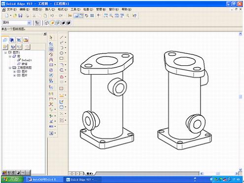
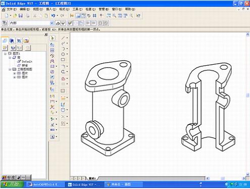
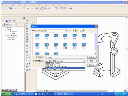
Combining some design software for application is an effective way to solve engineering problems. This article illustrates how to combine AutoCAD and SolidEdge for application, aiming to provide a reference for engineers and technicians. Figure 1 Axle and dimension identification of the machine If you use AutoCAD to draw the axonometric drawing in the axonometric mode directly, the biggest difficulty is the drawing of the intersecting line when the cylinder intersects the cylinder. Because the intersecting line is neither a circle nor an ellipse, use the circle command. Drawing an arc command or drawing an ellipse command cannot be accurately drawn. It must be approximated by a spline curve by making an auxiliary line, a special point and a general point. In addition, because the size of each part is relatively cumbersome, the time taken to draw such an isometric drawing will be much longer than the time to construct the 3D model of the part. In fact, the original impulse of a person when designing a part is three-dimensional, a three-dimensional entity with associated concepts such as color, material, hardness, shape, size, position, and related part manufacturing process. Therefore, we may wish to start with the three-dimensional model of the machine. In AutoCAD, although 3D model design can also be carried out, due to its data structure and technical reasons, the design update and modification are quite difficult, so you can consider using SolidEdge into 3D modeling. Open the SolidEdge cascading menu, as shown in Figure 2, click on "Solid Parts" to enter the part design module. In the part design interface, the three-dimensional model design of the machine is completed by using the commands of stretching, material removal, digging and chamfering, and is saved as shown in Fig. 3. In order to obtain the axial sectional view of the mechanism, a cutting entity must be created, and the front right portion of the mechanism is removed by using the cutout command on the basis of the previous entity, as shown in FIG. 4, and saved. Close the file. Figure 2 Open SolidEdge into the cascading menu Figure 3 Creating a 3D solid in the SolidEdge part design module Figure 4 Creating a cut model of the entity Click "Project" in the SolidEdge cascading menu to enter the drawing generation module. Use the "Drawing View Wizard" command to open the part document of the machine just created and select it in the "Named View" list. "Axis map", close the "drawing view wizard" dialog box, set the scale to 1:1 on the toolbar, and use the mouse to give the position of the isometric map on the drawing interface, as shown in Figure 5. Using the "Main View" command, pull out the axonometric view of our desired orientation based on the axonometric map, as shown in Figure 6. The three-dimensional model part file of the machine is also arranged in the same way in the drawing, and the unnecessary view is deleted, as shown in FIG. 7 . The next step is to edit the graphics and dimension. Although the size of the isometric drawing can be marked in the SolidEdge drawing module, it is more troublesome to adjust. Especially when you are unfamiliar with SolidEdge's annotation format setting and editing, you can't do it. . At this time, we may wish to use AutoCAD to complete the simple work of graphic editing and dimensioning. Figure 5 Generating an isometric drawing in the SolidEdge drawing generation module Figure 6 generates an isometric view in the other direction Figure 7 Adding the isometric view of the cut model Third, save as AutoCAD document Under the File menu, click Save As to open the Save As dialog box, as shown in Figure 8. In "Save as type", select "AutoCAD document (*dwg)", give the file name in the file name, and click "Save". This is a key step in converting a SolidEdge drawing document to an AutoCAD document, so that the saved document can be opened in AutoCAD. Figure 8 Save the generated graphics in the SolidEdge drawing generation module as AutoCAD documents. Open AutoCAD, enter the drawing interface of AutoCAD, click "Open" under the "File" menu, enter the "Select File" dialog box, select the file you just saved, click "Open", you can open the axis of the machine in the drawing area Mapping. After adjusting its display, as shown in Figure 9. At this time, the isometric drawing can not be edited and labeled, because each graphic corresponds to a tile. To edit, you must use the “decompose†command to decompose the graphic before editing and labeling. After decomposition, all the line types of the graph are thin solid lines. Use the Layer Property Manager to set the line width of the isometric drawing so that the outline of the isometric drawing is displayed in thick solid lines. At this time, the axial expansion coefficient of the isometric drawing is not 1, because the axial mapping generated in the SolidEdge drawing generation module is generated according to the formation projection of the isometric drawing, and the axial expansion coefficient is about 0.82. In order to dimension and view the size, it is easy to draw the axial expansion coefficient when the drawing is normal. Therefore, before the dimensioning, the axial expansion coefficient of the graphic should be changed to 1 by the “zoom†command. Figure 9 The generated graphics in the SolidEdge drawing generation module are opened in AutoCAD. In the AutoCAD format menu, set the "text style" and "label style", and set the corresponding layer, you can do the dimensioning, the specific steps are not described, as shown in Figure 10. Figure 10 Labeling with AutoCAD's text and dimensioning features As an engineering technician, in the actual work, faced with a large number of application software, we can not all be very skilled in application, may be more skilled in the common functions of some of the more commonly used software, for some not Commonly used features and some settings may not be familiar. Therefore, in the work, we should be good at combining different kinds of software for application, taking advantage of each other, avoiding shortcomings, improving our work efficiency, and making the work easier and faster. Applying AutoCAD to SolidEdge is an effective way to solve some engineering problems. Erlenmeyer flasks are widely use in cell suspension culture, medium confifiguration, mixing and storage.It is suitable for culturing cell lines with high oxygen requirements. It can also be used to culture bacteria, fungi and animal and plant cells in suspension. Compared with culture flasks, dishes and spinner flasks, it requires less work and is an economical solution. Cell Culture tool ideal for media preparation, mixing and storage.Reduces the chance of experimental personnel being infected during bacterial culture work. erlenmeyer flask bulk,erlenmeyer flask for bacterial culture,flask erlenmeyer,Erlenmeyer Flask,cheap erlenmeyer flask Yong Yue Medical Technology(Kunshan) Co.,Ltd , https://www.yongyuetube.com
AutoCAD, a software developed by Autodesk, has been widely used in manufacturing since its inception, with its powerful 2D drawing and editing capabilities. This is why it has long appeared on designer computers; however, its 3D modeling capabilities. And related editing tools are far less than other 3D design software, such as SolidEdge of US UGS Company, Solidworks of Solidworks, etc. With these 3D CAD design software, we can easily design and construct 3D solids, and can easily carry out physical design. Update, quickly generate basic engineering views; although you can edit and modify 2D drawings in SolidEdge, users who are used to drawing graphics with AutoCAD always feel that AutoCAD is not easy to operate. If we can use AutoCAD and SolidEdge ingeniously together, it will make the design and manufacture of the product easier. This article will use examples to illustrate how to combine AutoCAD and SolidEdge for application.
The legend in this paper is the axial view of the machine shown in Figure 1. The dimensions are shown below. 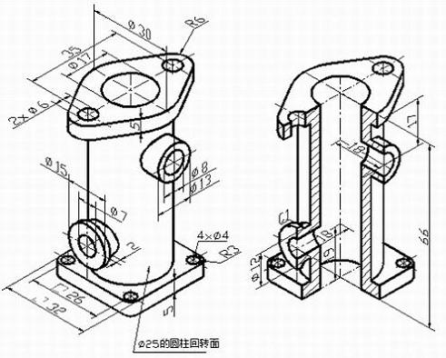
First, create a three-dimensional model 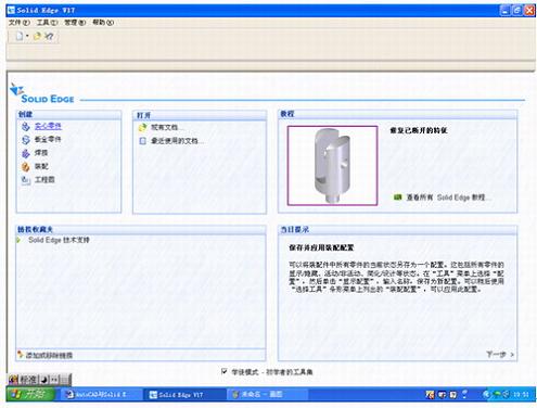
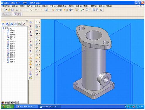
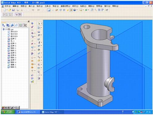
Second, create a drawing 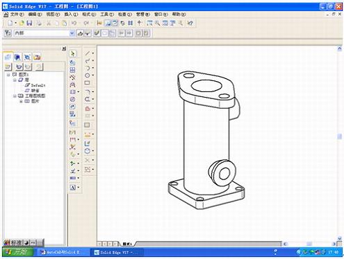
Fourth, open the drawing created by SolidEdge in AutoCAD 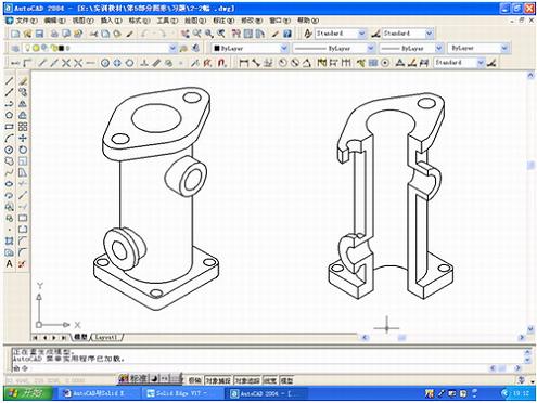
Five, dimensioning in AutoCAD 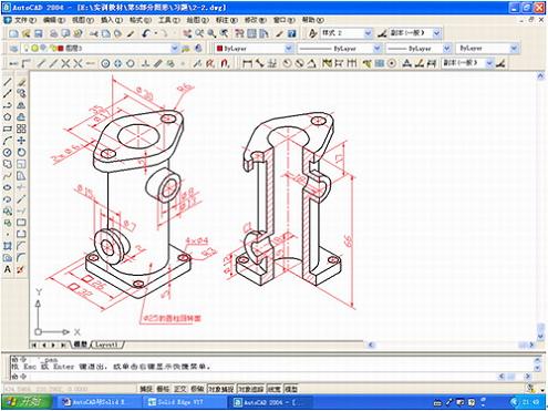
Conclusion